0) pipeline基础知识
vulkan的整个渲染流程实际上是一个pipeline, 也就是流水线的形式,通过在不同的管线阶段做相应的操作,最终我们可以得到渲染的结果。
实际上pipeline是整个图形渲染的核心,这里面也包括了太多的内容,具体如下图所示:
在下图中,黄色部分是我们可以编程实现的部分,绿色的部分是固定的,是我们不需要操作的部分。而实际上在大多数的场景下我们真正需要变成的就是Vertex shader和Fragment Shader。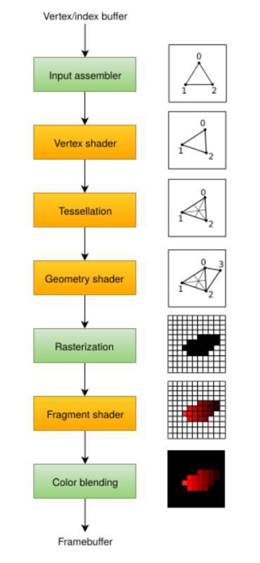
下面我们来介绍下上面这些部分的含义,而pipeline的整个流程实际上也是为了实现上面的内容。
input assembler 获取顶点数据,顶点数据的来源可以是应用程序提交的原始顶点数据,或是根据索引缓冲提取的顶点数据。
vertex shader 对每个顶点进行模型空间到屏幕空间的变换,然后将顶点数据传递给图形管线的下一阶段。
tessellation shaders 根据一定的规则对几何图形进行细分,从而提高网格质量。通常被用来使类似墙面这类不光滑表面看起来更自然。
geometry shader 可以以图元(三角形,线段,点) 为单位处理几何图形,它可以剔除图元,输出图元。有点类似于tessellation shader,但更灵活。但目前已经不推荐应用程序使用它,geometry shader 的性能在除了Intel 集成显卡外的大多数显卡上表现不佳。
rasterization 阶段将图元离散为片段。片段被用来在帧缓冲上填充像素。位于屏幕外的片段会被丢弃,顶点着色器输出的顶点属性会在片段之间进行插值,开启深度测试后,位于其它片段之后的片段也会被丢弃。
fragment shader 对每一个未被丢弃的片段进行处理,确定片段要写入的帧缓冲,它可以使用来自vertex shader 的插值数据,比如纹理坐标和顶点法线。
color blending 阶段对写入帧缓冲同一像素位置的不同片段进行混合操作。片段可以直接覆盖之前写入的片段,也可以基于之前片段写入的信息进行混合操作。
最终的结果写入到了framebuffer中。
图形管线的创建调用下面的函数实现:1
2
3
4
5
6
7VKAPI_ATTR VkResult VKAPI_CALL vkCreateGraphicsPipelines(
VkDevice device,
VkPipelineCache pipelineCache,
uint32_t createInfoCount,
const VkGraphicsPipelineCreateInfo* pCreateInfos,
const VkAllocationCallbacks* pAllocator,
VkPipeline* pPipelines);
pipelineCache 是管线缓存的句柄,这个我们在后续会介绍管线缓存的应用,如果不使用,则设置为VK_NULL_HANDLE
createInfoCount和pCreateInfos 是核心内容,它们表示了创建管线所需要的结构以及结构的数量。
这个结构很复杂,每一项都对应这上面图的一个小块内容。1
2
3
4
5
6
7
8
9
10
11
12
13
14
15
16
17
18
19
20
21typedef struct VkGraphicsPipelineCreateInfo {
VkStructureType sType; // VK_STRUCTURE_TYPE_GRAPHICS_PIPELINE_CREATE_INFO
const void* pNext; // 扩展
VkPipelineCreateFlags flags;
uint32_t stageCount;
const VkPipelineShaderStageCreateInfo* pStages;
const VkPipelineVertexInputStateCreateInfo* pVertexInputState;
const VkPipelineInputAssemblyStateCreateInfo* pInputAssemblyState;
const VkPipelineTessellationStateCreateInfo* pTessellationState;
const VkPipelineViewportStateCreateInfo* pViewportState;
const VkPipelineRasterizationStateCreateInfo* pRasterizationState;
const VkPipelineMultisampleStateCreateInfo* pMultisampleState;
const VkPipelineDepthStencilStateCreateInfo* pDepthStencilState;
const VkPipelineColorBlendStateCreateInfo* pColorBlendState;
const VkPipelineDynamicStateCreateInfo* pDynamicState;
VkPipelineLayout layout;
VkRenderPass renderPass;
uint32_t subpass;
VkPipeline basePipelineHandle;
int32_t basePipelineIndex;
} VkGraphicsPipelineCreateInfo;
1) flag位
flag表示一个位的掩码,表示管线的用途信息, 在vulkan_core.h文件中定义了它的枚举值,这个值告诉我们想要创建一个什么样子的管线。1
2
3
4
5
6
7
8
9
10
11
12
13
14
15
16
17
18
19
20
21
22
23
24
25typedef enum VkPipelineCreateFlagBits {
VK_PIPELINE_CREATE_DISABLE_OPTIMIZATION_BIT = 0x00000001,
VK_PIPELINE_CREATE_ALLOW_DERIVATIVES_BIT = 0x00000002,
VK_PIPELINE_CREATE_DERIVATIVE_BIT = 0x00000004,
VK_PIPELINE_CREATE_VIEW_INDEX_FROM_DEVICE_INDEX_BIT = 0x00000008,
VK_PIPELINE_CREATE_DISPATCH_BASE_BIT = 0x00000010,
VK_PIPELINE_CREATE_RAY_TRACING_NO_NULL_ANY_HIT_SHADERS_BIT_KHR = 0x00004000,
VK_PIPELINE_CREATE_RAY_TRACING_NO_NULL_CLOSEST_HIT_SHADERS_BIT_KHR = 0x00008000,
VK_PIPELINE_CREATE_RAY_TRACING_NO_NULL_MISS_SHADERS_BIT_KHR = 0x00010000,
VK_PIPELINE_CREATE_RAY_TRACING_NO_NULL_INTERSECTION_SHADERS_BIT_KHR = 0x00020000,
VK_PIPELINE_CREATE_RAY_TRACING_SKIP_TRIANGLES_BIT_KHR = 0x00001000,
VK_PIPELINE_CREATE_RAY_TRACING_SKIP_AABBS_BIT_KHR = 0x00002000,
VK_PIPELINE_CREATE_DEFER_COMPILE_BIT_NV = 0x00000020,
VK_PIPELINE_CREATE_CAPTURE_STATISTICS_BIT_KHR = 0x00000040,
VK_PIPELINE_CREATE_CAPTURE_INTERNAL_REPRESENTATIONS_BIT_KHR = 0x00000080,
VK_PIPELINE_CREATE_INDIRECT_BINDABLE_BIT_NV = 0x00040000,
VK_PIPELINE_CREATE_LIBRARY_BIT_KHR = 0x00000800,
VK_PIPELINE_CREATE_FAIL_ON_PIPELINE_COMPILE_REQUIRED_BIT_EXT = 0x00000100,
VK_PIPELINE_CREATE_EARLY_RETURN_ON_FAILURE_BIT_EXT = 0x00000200,
VK_PIPELINE_CREATE_DISPATCH_BASE = VK_PIPELINE_CREATE_DISPATCH_BASE_BIT,
VK_PIPELINE_CREATE_VIEW_INDEX_FROM_DEVICE_INDEX_BIT_KHR = VK_PIPELINE_CREATE_VIEW_INDEX_FROM_DEVICE_INDEX_BIT,
VK_PIPELINE_CREATE_DISPATCH_BASE_KHR = VK_PIPELINE_CREATE_DISPATCH_BASE,
VK_PIPELINE_CREATE_FLAG_BITS_MAX_ENUM = 0x7FFFFFFF
} VkPipelineCreateFlagBits;
typedef VkFlags VkPipelineCreateFlags;
2) shader加载
stageCount和pStages 定义了管线中的shader stage信息,也就是我们需要加载的shader信息
stageCount表示有几个shader,pStages是具体的shader信息,如下所示:1
2
3
4
5
6
7
8
9typedef struct VkPipelineShaderStageCreateInfo {
VkStructureType sType; //VK_STRUCTURE_TYPE_PIPELINE_SHADER_STAGE_CREATE_INFO
const void* pNext;
VkPipelineShaderStageCreateFlags flags;
VkShaderStageFlagBits stage; //表示shader是vertexShader还是fragShader等
VkShaderModule module; //具体加载的shader模型
const char* pName; //shader中的入口函数名称,一般是main
const VkSpecializationInfo* pSpecializationInfo;
} VkPipelineShaderStageCreateInfo;
而这里面的VkShaderModule是由shader文件创建的,如下所示:1
2
3
4
5
6
7
8
9
10
11
12
13VkShaderModule createShaderModule(const std::vector<char>& code) {
VkShaderModuleCreateInfo createInfo{};
createInfo.sType = VK_STRUCTURE_TYPE_SHADER_MODULE_CREATE_INFO;
createInfo.codeSize = code.size();
createInfo.pCode = reinterpret_cast<const uint32_t*>(code.data());
VkShaderModule shaderModule;
if (vkCreateShaderModule(device, &createInfo, nullptr, &shaderModule) != VK_SUCCESS) {
throw std::runtime_error("failed to create shader module!");
}
return shaderModule;
}
3) 顶点vertex信息
VkPipelineVertexInputStateCreateInfo这个结构主要是描述顶点信息是如何组织的。1
2
3
4
5
6
7
8
9typedef struct VkPipelineVertexInputStateCreateInfo {
VkStructureType sType;
const void* pNext;
VkPipelineVertexInputStateCreateFlags flags;
uint32_t vertexBindingDescriptionCount;
const VkVertexInputBindingDescription* pVertexBindingDescriptions;
uint32_t vertexAttributeDescriptionCount;
const VkVertexInputAttributeDescription* pVertexAttributeDescriptions;
} VkPipelineVertexInputStateCreateInfo;
其中VkVertexInputBindingDescription表示vertexBuffer缓冲中的顶点的绑定关系1
2
3
4
5typedef struct VkVertexInputBindingDescription {
uint32_t binding; // 结构的binding number
uint32_t stride; // buffer中的两个相邻元素的距离
VkVertexInputRate inputRate; /逐顶点还是逐实例渲染的方式
} VkVertexInputBindingDescription;
pVertexAttributeDescriptions表示结构的属性信息1
2
3
4
5
6typedef struct VkVertexInputAttributeDescription {
uint32_t location; // 属性再shader中的binding location
uint32_t binding; // 属性来源数据的binding number
VkFormat format; // 属性的格式以及size信息
uint32_t offset; // 属性再整个结构里面的偏移
} VkVertexInputAttributeDescription;
实际调用代码如下:1
2
3
4
5
6
7
8
9
10
11
12
13
14
15
16
17
18
19
20
21
22
23
24
25
26
27
28
29
30
31
32
33
34
35
36
37
38
39
40
41
42
43
44
45
46
47
48
49
50
51struct Vertex {
glm::vec3 pos;
glm::vec3 color;
glm::vec2 texCoord;
static VkVertexInputBindingDescription getBindingDescription() {
VkVertexInputBindingDescription bindingDescription{};
bindingDescription.binding = 0;
bindingDescription.stride = sizeof(Vertex);
bindingDescription.inputRate = VK_VERTEX_INPUT_RATE_VERTEX;
return bindingDescription;
}
static std::array<VkVertexInputAttributeDescription, 3> getAttributeDescriptions() {
std::array<VkVertexInputAttributeDescription, 3> attributeDescriptions{};
attributeDescriptions[0].binding = 0;
attributeDescriptions[0].location = 0;
attributeDescriptions[0].format = VK_FORMAT_R32G32B32_SFLOAT;
attributeDescriptions[0].offset = offsetof(Vertex, pos);
attributeDescriptions[1].binding = 0;
attributeDescriptions[1].location = 1;
attributeDescriptions[1].format = VK_FORMAT_R32G32B32_SFLOAT;
attributeDescriptions[1].offset = offsetof(Vertex, color);
attributeDescriptions[2].binding = 0;
attributeDescriptions[2].location = 2;
attributeDescriptions[2].format = VK_FORMAT_R32G32_SFLOAT;
attributeDescriptions[2].offset = offsetof(Vertex, texCoord);
return attributeDescriptions;
}
bool operator==(const Vertex& other) const {
return pos == other.pos && color == other.color && texCoord == other.texCoord;
}
};
VkPipelineVertexInputStateCreateInfo vertexInputInfo{};
vertexInputInfo.sType = VK_STRUCTURE_TYPE_PIPELINE_VERTEX_INPUT_STATE_CREATE_INFO;
auto bindingDescription = Vertex::getBindingDescription();
auto attributeDescriptions = Vertex::getAttributeDescriptions();
vertexInputInfo.vertexBindingDescriptionCount = 1;
vertexInputInfo.vertexAttributeDescriptionCount = static_cast<uint32_t>(attributeDescriptions.size());
vertexInputInfo.pVertexBindingDescriptions = &bindingDescription;
vertexInputInfo.pVertexAttributeDescriptions = attributeDescriptions.data();
3)图元装配
实际上这就是规定图元以什么格式装配,是点,线还是三角形或是其他的图形,还挺多的,不过一般都是triangle1
2
3
4
5
6
7typedef struct VkPipelineInputAssemblyStateCreateInfo {
VkStructureType sType;
const void* pNext;
VkPipelineInputAssemblyStateCreateFlags flags;
VkPrimitiveTopology topology;
VkBool32 primitiveRestartEnable; //布尔标志确定是否将特殊标记或顶点索引用作图元重启功能
} VkPipelineInputAssemblyStateCreateInfo;
4)曲面细分
VkPipelineTessellationStateCreateInfo这个结构是曲面细分用的,这也是一个可编程管线,如果我们要启用它,就还要设置一些其他的内容,大部分情况下,我们不需要做曲面细分,所以是不设置的。1
2
3
4
5
6typedef struct VkPipelineTessellationStateCreateInfo {
VkStructureType sType; // VK_STRUCTURE_TYPE_PIPELINE_TESSELLATION_STATE_CREATE_INFO
const void* pNext; //NULL或者指向VkPipelineTessellationDomainOriginStateCreateInfo结构
VkPipelineTessellationStateCreateFlags flags; // for future扩展用
uint32_t patchControlPoints; //每个patch的控制点的个数
} VkPipelineTessellationStateCreateInfo;
1 | typedef struct VkPipelineTessellationDomainOriginStateCreateInfo { |
5) 裁剪窗口
这又是一个概念,实际上是指我们渲染的结果以一种什么样的裁剪方式显示,主要包括视口和裁剪。
视口定义了图像到帧缓冲的映射关系。
裁剪矩形定义了哪一区域的像素实际被存储在帧缓存
一个比较形象的图如下所示: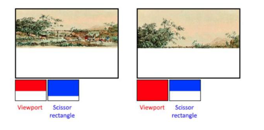
1
2
3
4
5
6
7
8
9typedef struct VkPipelineViewportStateCreateInfo {
VkStructureType sType;
const void* pNext;
VkPipelineViewportStateCreateFlags flags;
uint32_t viewportCount;
const VkViewport* pViewports;
uint32_t scissorCount;
const VkRect2D* pScissors;
} VkPipelineViewportStateCreateInfo;
1 | VkViewport viewport{}; |
6) 光栅化
光栅化定义了如何将物体映射到屏幕上的操作。1
2
3
4
5
6
7
8
9
10
11
12
13
14
15typedef struct VkPipelineRasterizationStateCreateInfo {
VkStructureType sType; //VK_STRUCTURE_TYPE_PIPELINE_RASTERIZATION_STATE_CREATE_INFO
const void* pNext; // 扩展
VkPipelineRasterizationStateCreateFlags flags; //遗留
VkBool32 depthClampEnable; // VK_TRUE 表示在近平面和远平面外的片段会被截断为在近平面和远平面上,而不是直接丢弃这些片段。这对于阴影贴图的生成很有用。使用这一设置需要开启相应的GPU 特性。
VkBool32 rasterizerDiscardEnable; // VK_TRUE 表示所有几何图元都不能通过光栅化阶段。这一设置会禁止一切片段输出到帧缓冲,一般位VK_FALSE
VkPolygonMode polygonMode; // 指定几何图元生成片段的方式
VkCullModeFlags cullMode; // 用于指定使用的表面剔除类型。我们可以通过它禁用表面剔除,剔除背面,剔除正面,以及剔除双面
VkFrontFace frontFace; // 用于指定顺时针的顶点序是正面,还是逆时针的顶点序是正面
VkBool32 depthBiasEnable;
float depthBiasConstantFactor;
float depthBiasClamp;
float depthBiasSlopeFactor;
float lineWidth; //用于指定光栅化后的线段宽度,它以线宽所占的片段数目为单位。线宽的最大值依赖于硬件,使用大于1.0f 的线宽,需要启用相应的GPU 特性。
} VkPipelineRasterizationStateCreateInfo;
7)多重采样
多重采样功能的开启实际上是为了减轻边缘走样问题的1
2
3
4
5
6
7
8
9
10
11typedef struct VkPipelineMultisampleStateCreateInfo {
VkStructureType sType;
const void* pNext;
VkPipelineMultisampleStateCreateFlags flags;
VkSampleCountFlagBits rasterizationSamples;
VkBool32 sampleShadingEnable;
float minSampleShading;
const VkSampleMask* pSampleMask;
VkBool32 alphaToCoverageEnable;
VkBool32 alphaToOneEnable;
} VkPipelineMultisampleStateCreateInfo;
8)深度与模板测试
1 | typedef struct VkPipelineDepthStencilStateCreateInfo { |
9)颜色混合
1 | typedef struct VkPipelineColorBlendStateCreateInfo { |
10)管线布局
实际上这里是因为我们管线要绑定动态的描述符集和推常量,因此需要提前在管线的创建阶段给两者留出位置。1
2
3
4
5VKAPI_ATTR VkResult VKAPI_CALL vkCreatePipelineLayout(
VkDevice device,
const VkPipelineLayoutCreateInfo* pCreateInfo,
const VkAllocationCallbacks* pAllocator,
VkPipelineLayout* pPipelineLayout);
1 | typedef struct VkPipelineLayoutCreateInfo { |
11)renderPass
在创建管线的时候,还要指定renderpass以及使用到的subpass在subpass数组中的索引,这是因为一个renderpass可能存在多个subpass,而这些subpass可能被不同的pipeline使用,同时也可能存在多个renderpass。
12)衍生管线
basePipelineHandle 和basePipelineIndex 成员变量用于以一个创建好的图形管线为基础创建一个新的图形管线。当要创建一个和已有管线大量设置相同的管线时,使用它的代价要比直接创建小,并且,对于从同一个管线衍生出的两个管线,在它们之间进行管线切换操作的效率也要高很多。我们可以使用basePipelineHandle 来指定已经创建好的管线,或是使用basePipelineIndex 来指定将要创建的管线作为基础管线,用于衍生新的管线。如果我们只使用一个管线,所以将这两个成员变量分别设置为VK_NULL_HANDLE 和-1,不使用基础管线衍生新的管线。这两个成员变量的设置只有在VkGraphicsPipelineCreateInfo 结构体的flags 成员变量使用了VK_PIPELINE_CREATE_DERIVATIVE_BIT 标记的情况下才会起效。
13)最后我们在创建了pipeline后,我们还是要销毁我们之前加载的shader模型资源的。
1 | vkDestroyShaderModule(device, fragShaderModule, nullptr); |
14) 最最后,我们的完整代码如下所示:
1 | 创建一个pipeline,需要配置如此多的内容。 |